MIC300 Series Protection & Control Device
The MIC300 Series Protection & Control Device consists of a comprehensive protection & control device (including circuit, transformer, motor, capacitor, busbar protection functions) and an anti-islanding protection & control device. Suitable for 10kV and below grid consumption systems and small-scale distributed 400V low-voltage photovoltaic grid connection projects. It uses a high-performance 32-bit CPU integrating protection, control, and communication functions into one unit.
Product Overview
Introduction to MIC300 Series
The MIC300 Series device consists of a comprehensive protection & control device (including circuit, transformer, motor, capacitor, busbar protection functions) and an anti-islanding protection & control device. Suitable for 10kV and below grid consumption systems and small-scale distributed 400V low-voltage photovoltaic grid connection projects.
It uses a high-performance 32-bit CPU integrating protection, control, and communication functions into one unit. The device can be installed centrally in groups, or directly on the switch cabinet for distributed control. The device offers high stability, flexibility, maintainability, and adaptability to different site conditions.
High Integration
Uses a high-performance 32-bit CPU integrating protection, control, and communication functions, reducing device count and wiring complexity.
Comprehensive Protection
Provides comprehensive protection functions including motor start, instantaneous overcurrent, definite-time overcurrent, overcurrent, inverse-time overcurrent, post-acceleration protection, etc.
Precise Measurement Control
Measures primary and secondary values, features 10 remote signal inputs, 4 independent relay outputs, meeting various measurement control requirements.
Application Scope
The MIC300 Series Protection & Control Device is suitable for various application scenarios:
Suitable for 10kV and below grid consumption systems, providing comprehensive protection and control functions.
Suitable for small-scale distributed 400V low-voltage photovoltaic grid connection projects, providing anti-islanding protection.
Suitable for protection and control of various industrial power equipment such as transformers, motors, capacitors, and busbars.
Supports MODBUS RTU communication protocol, can be integrated with SCADA systems to realize distribution automation.
Technical Specifications
Main Technical Specifications
| Item | Unit | Parameter |
|---|---|---|
| Rated setting current | A | 5A or 1A (specify when ordering) |
| Rated voltage | V | 100V (MIC300-1S), 380V (MIC300-5S) |
| Frequency measurement range | Hz | 35Hz-65Hz |
| Operating power (AC) | V | AC100V~264V; 50Hz±0.5Hz |
| Operating power (DC) | V | DC100V~264V, ripple factor ≤5% |
| Power consumption (DC power circuit) | W | ≤3W during normal operation; ≤5W during protection action |
| Overload capability of current input circuit | - | 2x rated current continuous; 10x rated current for 10s; 20x rated current for 1s |
| Setting accuracy current error | - | ≤ ±5% |
| Frequency setting error | Hz | ≤ ±0.01Hz |
| Instantaneous unit operating time | ms | ≤ 35ms (when stimulus ≥1.2x setting value) |
Environmental Conditions
| Item | Parameter |
|---|---|
| Normal operating temperature | -20℃~+60℃ |
| Relative humidity | Maximum 90% relative humidity, no condensation inside product |
| Altitude | ≤2000m |
| Protection rating | IP20 |
| Installation method | Centralized group installation or direct installation on switch cabinet |
Electromagnetic Compatibility Performance
The MIC300 Series device features excellent electromagnetic compatibility performance, complying with relevant national standards:
The device withstands contact discharge ±8kV and air discharge ±15kV as specified in GB/T14598.26-2015, meeting performance criterion A.
The device withstands class A fast transient disturbance tests (voltage: ±4kV, repetition rate: 5kHz, duration: 60s per polarity) as specified in GB/T14598.26-2015.
The device withstands class A surge disturbance tests (line-earth 4kV, line-line 2kV) as specified in GB/T14598.26-2015.
The device withstands radiated RF electromagnetic field disturbance tests of 10V/m as specified in GB/T14598.26-2015, meeting criterion A requirements.
Insulation Performance
Insulation resistance between each conductive circuit and ground, and between circuits without electrical connection is not less than 100MΩ.
Between each conductive circuit and ground, and circuits without electrical connection: For circuits with nominal insulation voltage 63V~250V, withstand 2.0kV power frequency voltage; for ≤63V, withstand 500V for 1 minute without flashover, breakdown or component damage.
Between each conductive circuit and ground, and circuits without electrical connection: For circuits with nominal insulation voltage 63V~250V, withstand standard lightning impulse 1.2/50μs, open circuit voltage 5kV; for ≤63V, withstand 1kV; no insulation breakdown or damage.
Model Functions
Model Configuration Comparison
| Model Name | Function Configuration | Application Scenario |
|---|---|---|
| MIC300-1S Comprehensive Protection & Control Device |
10kV and below grid consumption systems, including circuit, transformer, motor, capacitor, busbar protection functions | |
| MIC300-5S Anti-Islanding Protection & Control Device |
Small-scale distributed 400V low-voltage photovoltaic grid connection projects, preventing islanding operation |
Measurement Control Functions
Measurement Functions
UA, UB, UC, UAB, UBC, UCA, IA, IB, IC, P, Q, COS, F
Ua, Ub, Uc, Uab, Ubc, Uca, Ia, Ib, Ic, P, Q, COS, F
Switch Quantity I/O
Features 10 remote signal input collection channels, supporting passive switch input
4 independent relay outputs, configurable for different functions such as trip, close, alarm, etc.
Communication Functions
1 RS485 communication interface, supporting long-distance data transmission
MODBUS RTU protocol, compatible with major SCADA systems
Protection events, alarm events, remote signal events, operation records cyclically store up to 128 latest events; self-check info stores up to 16 latest events
Product Features
Core Features
High-Performance Processor
Uses embedded 32-bit microprocessor, strong data processing capability, fast response, high calculation accuracy.
Large Capacity Storage
Comprehensive device operation and fault information recording, providing sufficient data for operation optimization and fault analysis. Stores up to 128 latest action reports.
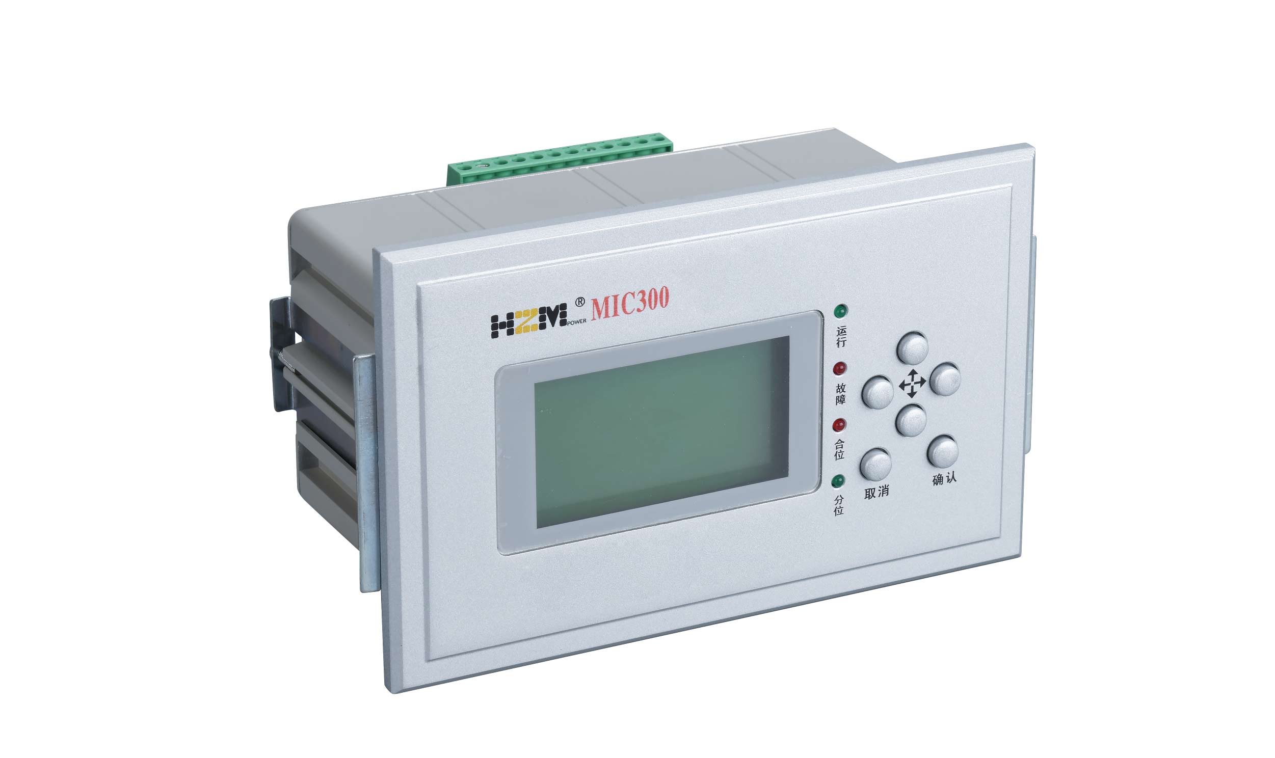
User-Friendly HMI
User-friendly interface, simple operation, six indicator lights show real-time device status, clear Chinese LCD display.
High Electromagnetic Compatibility
High-standard EMC performance, enclosed design, meeting strict requirements for switchboard mounting.
Flexible Installation Methods
Compact size, can be installed centrally in groups, distributed on switch cabinets, or locally in outdoor switchgear.
Multi-Zone Setting Management
Provides 8 setting zones, non-volatile during power loss, meeting various operating mode changes.
Rich Input Interface
10 switch input ports, facilitating different site condition selections, supporting multiple signal connections.
Complete Event Recording
Protection events, alarm events, remote signal events, operation records cyclically store up to 128 latest events; self-check info stores up to 16 latest events.
Indicator Light Explanation
Protection Functions Detailed Explanation
Comprehensive Protection Functions MIC300-1S
Function description: Monitors motor starting process, blocks certain protection functions during start to prevent false tripping.
Start condition: Motor start enabled; max protection current among ia, ib, ic ≥0.2*le; condition duration → motor start time.
Start complete: Motor start time reached, start finished, character "M" displayed at bottom right corner (M blinks during start, stops after start), enabling definite-time overcurrent, overcurrent, inverse-time overcurrent, overload.
Stop judgment: Circuit breaker open position (A10=1) or max protection current among ia, ib, ic <0.04In; either condition met, motor stops.
Function description: Instantaneous current protection for fast clearing of severe faults.
Action condition: Instantaneous overcurrent enabled; max protection current among ia, ib, ic ≥ instantaneous overcurrent setting.
Action result: Device immediately drives trip output 1J (A01/A02), simultaneously drives trip alarm relay 3J (A05/A06), LCD displays trip info, panel trip light lights.
Function description: Time-delayed current protection, coordinating with instantaneous overcurrent for selective protection.
Action condition: Definite-time overcurrent enabled; max protection current among ia, ib, ic ≥ definite-time overcurrent setting; condition duration ≥ definite-time overcurrent delay.
Action result: Device immediately drives trip output 1J (A01/A02), simultaneously drives trip alarm relay 3J (A05/A06), LCD displays trip info, panel trip light lights.
Function description: Backup current protection for overload and remote faults.
Action condition: Overcurrent enabled; max protection current among ia, ib, ic ≥ overcurrent setting; condition duration ≥ overcurrent delay.
Action result: Device immediately drives trip output 1J (A01/A02), simultaneously drives trip alarm relay 3J (A05/A06), LCD displays trip info, panel trip light lights.
Function description: Protection that automatically adjusts operating time based on fault current magnitude.
Inverse-time characteristics: Three inverse-time curves (based on IEC225-4):
- General inverse: t = 0.14/(I/ρ)^0.02 * Tρ
- Very inverse: t = 13.5/(I/ρ)^1-1 * Tρ
- Extremely inverse: t = 80/(I/ρ)^2-1 * Tρ
Note: Overcurrent and inverse-time overcurrent share numerical and time settings; if both enabled, inverse-time overcurrent is invalid.
Anti-Islanding Protection Functions MIC300-5S
Function description: Monitors system frequency, prevents equipment damage due to abnormal frequency.
Overfrequency protection: Overfrequency stage I/II enabled; frequency f ≥ overfrequency stage I/II setting; protection current ≥0.04In or closed position signal = 1; condition duration ≥ overfrequency stage I/II delay.
Underfrequency protection: Underfrequency stage I/II enabled; protection current ≥0.04In or closed position signal = 1; frequency f < underfrequency stage I/II setting; condition duration ≥ underfrequency stage I/II delay.
Function description: Automatic reconnection after system voltage returns to normal, restoring power supply.
Action condition: Auto voltage reconnection enabled; voltage lower limit < Uab, Ubc, Uca < voltage upper limit; open position signal = 1; distributed generation side voltage Ux <0.3Un; no blocking signal; condition duration ≥ voltage reconnection delay.
Action result: Drives electrical reset 3J (A05/A06), then drives close output 2J (A03/A04), LCD displays voltage reconnection.
Function description: Automatic reconnection after power recovery, suitable for distributed generation systems.
Action condition: Power recovery reconnection enabled; secondary active power P ≥ power recovery setting; open position signal = 1; no blocking signal; condition duration ≥ power recovery delay.
Action result: Drives electrical reset 3J (A05/A06), then drives close output 2J (A03/A04), LCD displays power recovery reconnection.
Function description: Detects system harmonic content, prevents equipment damage due to excessive harmonics.
Action condition: Harmonic detection enabled; any phase total harmonic distortion THDUa, THDUb, THDUc ≥ harmonic content setting; condition duration ≥ harmonic detection delay.
Action result: Device immediately drives trip output 1J (A01/A02), simultaneously drives signal relay 4J (A07/A08).
Hardware Configuration
Device Hardware Structure
- 4 relay outputs: trip output A01-A02, close output A03-A04, trip alarm output A05-A06, warning alarm output A07-A08
- 10 passive switch inputs: A09~A18, A19 is common input terminal
- Power input port: A20 L/DC+, A21 N/DC-, A22 FG (device ground)
- RS485 communication interface: B01-B02
- Analog input ports: supports 4 voltage inputs, 4 current inputs
- AC power: AC100V~264V; 50Hz±0.5Hz; THD ≤15%
- DC power: DC100V~264V, ripple factor ≤5%
- Power consumption: DC power circuit ≤3W normal; ≤5W during protection action
A09: closed position signal, A10: open position signal, A11: backup/main transformer open, A12: backup/load control trip, A13: backup/heavy gas, A14: backup/light gas, A15: backup/overtemperature, A16: backup/temperature rise, A17: reclose blocking (manual isolation signal), A18: remote
Schematic Preview
MIC300 Series Device Schematic
When changing Y connection to M connection, connect B1 to terminal B05 position
Switch inputs 3-10 definition varies by application object, refer to switch input definition table for details
Setting Value Configuration Explanation
MIC300 Series device provides comprehensive setting value configuration, users can adjust protection parameters based on actual requirements:
01 Motor start, 02 Instantaneous overcurrent, 03 Definite-time overcurrent, 04 Overcurrent, 05 Inverse-time overcurrent, 06 Post-acceleration, 07 Overload, 08 Zero-sequence overcurrent, 09 Reclosing, 10 Mismatched reclosing, etc., all configurable as "On" or "Off".
Includes motor rated current, instantaneous overcurrent setting, definite-time overcurrent setting, overcurrent setting, overload setting, zero-sequence overcurrent setting, overvoltage setting, undervoltage setting, underfrequency load shedding setting, etc., configurable based on site conditions.
Serial port communication address, baud rate, parity, language selection, relay output display, output transmission enable, etc.
PT primary nominal value, PT secondary nominal value, measurement CT primary nominal value, protection CT primary nominal value, zero-sequence CT secondary nominal value, PT number, zero-sequence voltage/current self-generation, phase current polarity, etc.
Setting Value Calculation Formula
le2 = P ÷ (√3 × U1 × N1 × N)
Where: le2 is secondary current value at rated load capacity; P is rated load capacity; U1 takes voltage level (10kV takes 10, 6kV takes 6); N1 is CT ratio (e.g., 200/5 CT has N1=40).
Operation Guide
Menu Structure and Operation
Key Function Explanation
Signal reset, restores stored signals
Enter submenu, confirm modification execution
Cancel current operation, return to upper menu
Move cursor up/down, menu selection, display line toggle, number increase/decrease
Move cursor left/right; in protection/alarm event records, press direction keys to return to upper menu or view action record values
Contrast adjustment: "Enter"+"↑" increases contrast (suitable for low temperature), "Enter"+"↓" decreases contrast (suitable for high temperature). Contrast is non-volatile, restored after power-up.
Operation Process
Setting and Querying Setting Values
- From main menu → Parameter Setting, select parameter type to set, press "Enter" to enter setting interface.
- Press "Enter" again to display cursor, then parameter value can be set.
- Use "←""→" to adjust cursor position, "↑""↓" to adjust setting value.
- After setting parameter value, press "Enter" or "Cancel" to exit that parameter setting.
- Press "↑" or "↓" to select next parameter to set.
- When done setting parameters of that type, press "Cancel" to enter password verification interface, enter password 1000.
- Press "Enter" to save settings and return to main menu; if "Cancel" is pressed on password verification interface, modifications are discarded and return to main menu.
Viewing Event Records
- From main menu → Event Records, select event type to view.
- Press Enter to enter event information display.
- Use "↑""↓" keys to query events in order.
- Use "←""→" keys to switch current event information page.
Local Debugging
- From main menu → Local Debugging, enter debugging interface, password 1000.
- Output transmission test: First set [System Parameters] → [Output Transmission Enable] to "1", then main menu → Local Debugging → Output Transmission, enter output transmission test page, select corresponding relay output then press Enter to perform output test.
- Event simulation: Main menu → Local Debugging → Event Simulation, select events such as protection, alarm, remote signal, self-check, etc., can be queried via event records after completion.
- System reset: Used to clear event records from testing or restore default settings.
Important Notes
- This manual is applicable only to MIC300-1S Comprehensive Protection & Control Device.
- The device terminal diagrams and principle diagrams default to passive switch inputs and operating circuits.
- Please read this manual carefully, and adjust, test, and operate according to the manual's rules. In case of any discrepancies, refer to accompanying documentation as standard.
- To avoid device damage, it is strictly forbidden to plug/unplug device connectors or touch chips and components on the PCB while powered.
- Please use qualified instruments and test equipment to test and inspect the device.
- If the device behaves abnormally or requires repair, please contact our company's service hotline immediately.
- This manual and the product may be modified; please pay attention to the latest version of materials. Protection information point table has separate file explanation.
Contact Us
Service Hotline
400 881 0501
Official Website
Company Information
Hertzman (Hangzhou) Power Technology Co., Ltd.
Copyright Statement
MIC300® is a registered trademark of Hertzman (Hangzhou) Power Technology Co., Ltd., rights protected by trademark law.
Request Complete Product Manual
To request the PDF version of the complete product manual, technical specifications, or customized solutions, please fill in the information below. Our technical consultant will contact you as soon as possible.