EXE-HIC3.0 Series Electronic Molded Case Air Circuit Breaker
Suitable for AC 50Hz power distribution networks with rated insulation voltage 1000V, rated working voltage 400V or 690V, rated working current up to 1600A. Used for distributing electrical energy and protecting circuits and equipment from damage caused by overload, short circuit, undervoltage, and other faults.
Product Overview
EXE-HIC3.0 Series Electronic Molded Case Circuit Breaker (hereinafter referred to as the circuit breaker) is suitable for AC 50Hz power distribution networks with rated insulation voltage 1000V, rated working voltage 400V or 690V, rated working current up to 1600A. It is used for distributing electrical energy and protecting circuits and equipment from damage caused by overload, short circuit, undervoltage, and other faults.
According to the level of rated breaking capacity, the circuit breaker is divided into M and H types. This circuit breaker features small size, high breaking capacity, short arcing distance, and high accuracy.
The circuit breaker complies with standards: GB14048.2, IEC60947-2
Normal Working Conditions
- Altitude: 2000m and below.
- Ambient air temperature not higher than +70℃ and not lower than -20℃, with a 24-hour average not exceeding +50℃.
- Atmospheric conditions: Relative humidity of the atmosphere does not exceed 95% when the ambient air temperature is +70℃. Higher relative humidity is allowed at lower temperatures. The average maximum relative humidity of the wettest month is 85%, taking into account condensation on the product surface due to temperature changes.
- Pollution degree: Pollution degree is Level S
- Installation category: Installation category is III.
Product Model Naming Rules
| Component | Meaning | Options |
|---|---|---|
| EXE | Product Series | Fixed |
| Frame Current | Circuit breaker frame current | 125, 250, 400, 630, 800, 1250, 1600 |
| Breaking Capacity | Circuit breaker breaking capacity level | M: Basic type, H: High breaking capacity |
| Rated Current | Circuit breaker rated working current | 125, 250, 400, 630, 800, 1250, 1600 |
| Number of Poles | Circuit breaker number of poles | 3P, 4P |
| HIC3.0 | Electronic trip unit | Fixed |
| Accessories | Optional accessory types | AX: Auxiliary, AL: Alarm, MX: Shunt trip, MN: Undervoltage, MCH: Electric operation, HCH: Manual operation |
| Communication Solution | Communication interface | COM1, COM3, COM4 |
Product Display
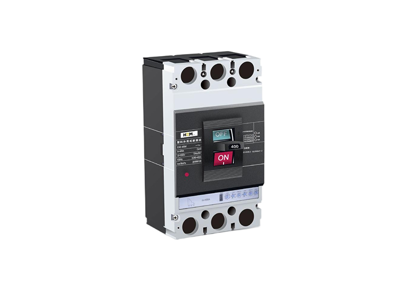
EXE-HIC3.0 Series Electronic Molded Case Air Circuit Breaker
Electronic trip, intelligent protection
Product Features
The EXE-HIC3.0 Series Electronic Molded Case Air Circuit Breaker uses advanced electronic trip technology to provide more accurate protection and more reliable performance.
- Electronic trip for more accurate protection
- High breaking capacity, safe and reliable
- Short arcing distance, saves space
- Compact size, easy installation
- Complies with GB14048.2, IEC60947-2 standards
- Multiple communication solutions available
Note: The image shows the typical appearance of the EXE-HIC3.0 series circuit breaker. Actual products may vary depending on model and configuration.
Technical Specifications
| Parameter Name | M Type | H Type | Unit |
|---|---|---|---|
| Rated Insulation Voltage | 1000 | V | |
| Rated Working Voltage | 400/690 | V | |
| Rated Frequency | 50 | Hz | |
| Frame Current Rating | 125, 250, 400, 630, 800, 1250, 1600 | A | |
| Electronic Trip Unit | HiLogic 3.0 | - | |
| Frame Current (A) | M Type Breaking Capacity (kA) | H Type Breaking Capacity (kA) | Utilization Category |
|---|---|---|---|
| 125 | 35 | 50 | B |
| 250 | 35 | 50 | |
| 400 | 35 | 50 | |
| 630 | 35 | 50 | |
| 800 | 35 | 50 | |
| 1250 | 35 | 50 | |
| 1600 | 35 | 50 |
| Protection Function | Setting Range | Accuracy | Action Time |
|---|---|---|---|
| Overload Protection (L) | 0.4~1×In | ±5% | Adjustable |
| Short-time Delay Short Circuit (S) | 1.5~10×In | ±10% | 0.1~0.4s |
| Instantaneous Short Circuit (I) | 1.5~12×In | ±10% | ≤30ms |
| Ground Fault (G) | 0.2~0.8×In | ±10% | 0.1~0.4s |
| Undervoltage Protection | 0.35~0.7×Ue | ±5% | 1~3s |
Installation Dimensions
3-Pole Circuit Breaker Dimensions (125-800A)
| Model | W(mm) | W1(mm) | L(mm) | H(mm) | H1(mm) |
|---|---|---|---|---|---|
| EXE-125 HIC3.0 3P | 92 | 60 | 150 | 110 | 96 |
| EXE-250 HIC3.0 3P | 107 | 70 | 165 | 112 | 98 |
| EXE-400 HIC3.0 3P | 150 | 96 | 260 | 155 | 116 |
| EXE-630 HIC3.0 3P | 130 | 96 | 260 | 155 | 116 |
| EXE-800 HIC3.0 3P | 210 | 140 | 280 | 162 | 122 |
3-Pole Circuit Breaker Dimensions (1250-1600A)
| Model | W(mm) | L(mm) | H(mm) | H1(mm) | H2(mm) |
|---|---|---|---|---|---|
| EXE-1250 HIC3.0 3P | 210 | 468 | 329 | 188 | 154 |
| EXE-1600 HIC3.0 3P | 210 | 507 | 329 | 188 | 154 |
4-Pole Circuit Breaker Dimensions (125-800A)
| Model | W(mm) | W1(mm) | L(mm) | H(mm) | H1(mm) |
|---|---|---|---|---|---|
| EXE-125 HIC3.0 4P | 122 | 90 | 150 | 110 | 96 |
| EXE-250 HIC3.0 4P | 142 | 105 | 166 | 112 | 98 |
| EXE-400 HIC3.0 4P | 198 | 96 | 260 | 155 | 116 |
| EXE-630 HIC3.0 4P | 198 | 96 | 260 | 155 | 116 |
| EXE-800 HIC3.0 4P | 282 | 210 | 280 | 162 | 122 |
4-Pole Circuit Breaker Dimensions (1250-1600A)
| Model | W(mm) | L(mm) | H(mm) | H1(mm) | H2(mm) |
|---|---|---|---|---|---|
| EXE-1250 HIC3.0 4P | 280 | 468 | 329 | 188 | 154 |
| EXE-1600 HIC3.0 4P | 280 | 468 | 329 | 188 | 154 |
Plug-in Type Outline and Installation Dimensions
| Model | a(mm) | b(mm) | c(mm) | e(mm) | h(mm) |
|---|---|---|---|---|---|
| EXE-125 HIC3.0 | 48 | 82 | 56 | 132 | 64 |
| EXE-250 HIC3.0 | 56 | 84 | 54 | 147 | 71.5 |
| EXE-400 HIC3.0 | 65 | 160 | 129 | 220 | 83.5 |
| EXE-630 HIC3.0 | 65 | 160 | 129 | 220 | 83.5 |
| EXE-800 HIC3.0 | 72 | 171 | 146 | 240 | 92 |
Drawer Type/Fixed Separation Type Manual Rotary Operating Mechanism
| Model | L(mm) | W(mm) | H(mm) | Mounting Bolts |
|---|---|---|---|---|
| EXE-125/3P | 129 | 30 | 52 | M4×75 |
| EXE-125/4P | 129 | 30 | 52 | M4×75 |
| EXE-250/3P | 144 | 35 | 56 | M4×36 |
| EXE-250/4P | 144 | 35 | 56 | M4×36 |
| EXE-400/3P | 195 | 138 | 87 | M4×56 |
| EXE-400/4P | 195 | 186 | 87 | M4×56 |
| EXE-800/3P | 243 | 198 | 94 | M5×52 |
| EXE-800/4P | 243 | 70 | 94 | M5×125 |
Accessories Information
Undervoltage Trip Unit
AX230 - AC230V
AX400 - AC400V
Shunt Trip Unit
MX24 - DC24V
MX230 - AC230V
MX400 - AC400V
Alarm Contact
1 NO + 1 NC
Auxiliary Contact
Auxiliary Contact AX
Electric Operating Mechanism
MCH230 - AC230V
MCH400 - AC400V
Auxiliary Torque Operating Handle
Applicable range: 400A, 800A
Extension Bar
125A, 250A
400A, 800A
Rear Connection
3-pole/4-pole
Safety Precautions
- Install on flame-retardant materials such as metal.
- Do not install in environments containing explosive gases, otherwise there is a risk of explosion.
- Do not install in damp places.
- Do not operate the circuit breaker with wet hands, otherwise electric shock may occur.
- Do not install where external magnetic field is greater than the Earth's magnetic field, otherwise the circuit breaker will not work properly.
- Do not install where vibration exceeds 5G.
- Do not install where the gas medium can corrode metals and damage insulation.
- Maintenance and inspection must be performed by professional technicians.
Operation Guide
1: Pre-operation Inspection and Preparation
Before operation, check the following items:
- Check that wiring is correct, especially that the input terminals (1, 3, 5) of the circuit breaker should be connected to the power line, and the output terminals (2, 4, 6) should be connected to the load line.
- Confirm that there is no short circuit or ground fault between terminals or exposed live parts.
- Confirm that terminal connections and fixing screws are tight and not loose.
- If the circuit breaker is equipped with an undervoltage trip unit, the trip unit should be energized first before the circuit breaker is allowed to close.
2: Trial Operation
After confirming all items are normal, trial operation can be performed:
- Adjust Ir1, Ir2, I2, Ir3, Ir0 on the front cover as needed by the user.
- Switch the operating handle to apply power (must meet condition 1.4 above).
- After the main circuit of the circuit breaker is energized, press the trip button. The circuit breaker should trip, and the operating handle should be in the tripped position.
3: Operation
If step 2 is satisfied, operation can proceed according to step 2.2.
Warranty Period and After-sales Service
1: Warranty Period
Under proper storage and usage conditions, within 18 months from the date of shipment from our factory, if the circuit breaker seal is intact and the product is damaged or cannot work normally due to manufacturing quality problems, our factory will be responsible for free repair or replacement.
However, if the fault is caused by the following reasons, even during the warranty period, repair or replacement will be charged:
- Due to misuse, self-modification, or improper maintenance.
- Use beyond the requirements of standard specifications.
- Damage caused by dropping during transportation or installation process after purchase.
- Due to earthquakes, fires, lightning strikes, abnormal voltage, other disasters and secondary disasters.
2: After-sales Service
- In case of failure, please contact the supplier or our after-sales service department.
- Repair or replacement within the warranty period: If the fault is caused by manufacturing problems from our factory, free repair will be provided until replacement.
- Repair or replacement after the warranty period: If the function can be maintained after repair, charged repair will be provided; if it cannot work normally after repair, charged replacement will be provided.